
Article
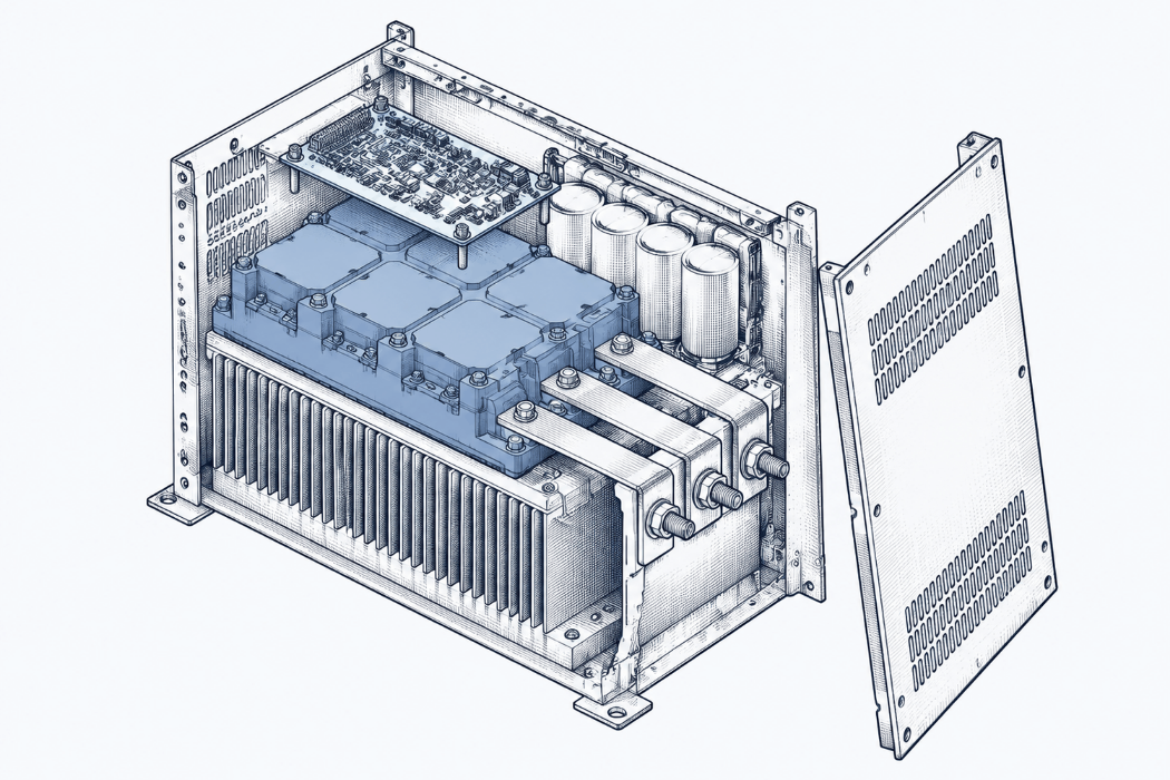
IGBT failure in a VFD: symptoms and a diode-mode test
A failed IGBT shows as a short-circuit, overcurrent or DC bus fuse fault that stays with the motor off, or rough running with unbalanced output. How to diode-test the output stage with the drive dead, what the readings mean, and the gate checks when it passes. Yaskawa, Danfoss, Siemens refs.
Short answer: A failed IGBT usually shows as a short-circuit, overcurrent or DC bus fuse fault that stays with the motor cable lifted, or as rough running with unbalanced output voltage. To test it, isolate the drive, prove the DC bus is discharged, disconnect the motor, and diode-test each output against DC+ and DC−. A pass doesn't fully clear it.
Applies to: three-phase AC drives with a diode rectifier, DC bus and six-IGBT output stage, with worked references for Yaskawa E7, Danfoss VLT FC high-power units, Siemens MICROMASTER 440 and Rockwell PowerFlex 750 frames 5 and 6. Terminal names, readings and test points differ between drives, so check your own manual · Manuals used: Yaskawa E7 Drive User Manual TM.E7.01; Danfoss High Power Service Manual for VLT FC Series MG.90.L1.02; Siemens MICROMASTER 440 Parameter List 6SE6400-5BB00-0BP0 (Issue 01/06); Rockwell PowerFlex 750-Series TotalFORCE Hardware Service Manual, frames 5 and 6 (online); Semikron Danfoss Application Note AN 20-003 · Last verified: 26 Oct 2026
What does it look like when the drive is the last suspect?
Our overcurrent post ended at one point: the drive faults with the motor cable lifted, so the problem is inside the drive. The usual next question is whether the output stage has failed, and how you prove it on site.
Someone asked exactly that on PLCtalk in September 2014. Amar88, who said he was new to the field, wanted to check the IGBT module of a Siemens SIMOVERT VC drive "while input is connected to drive". The first reply, from jraef, was: "You do not. You can get killed." A few posts later keithkyll gave the safe version. With the drive unpowered and the motor disconnected, diode-test across the outputs. If any of the IGBTs are shorted, he wrote, "they will read close to zero Ohms."
That's the whole method in two posts. This page fills in the rest: the symptoms that point to the output stage, the full test with the drive dead, what the readings mean, and what the test can't tell you.
What are the symptoms of a failed IGBT?
The drive rarely says "IGBT" outright. The manuals list the output stage among the causes of a handful of faults and symptoms:
- A short-circuit or hardware fault that won't clear with the motor disconnected. On the MM440, F0022 (hardware monitoring) covers a DC link overcurrent, which Siemens equates with an IGBT short-circuit, plus a braking chopper short, a ground fault on some sizes, and an I/O module not seated properly. Siemens says the power module can't tell you which of these happened. For a permanent F0022 the check is to disconnect the motor cable. If the fault still occurs with every external cable off except the supply, the drive is very probably defective (Parameter List p. 309).
- Overcurrent that follows the drive, not the motor. Yaskawa's E7 overcurrent entry includes a shorted drive output phase to phase. The suggested checks are to run the drive without the motor and look for a phase-to-phase short at the drive output (User Manual p. 6-5). Danfoss's Alarm 16 is a short circuit in the motor or at the motor terminals (Service Manual p. 66), so lift the motor cable before you blame the drive.
- An open DC bus fuse. On the E7, PUF means the DC bus fuse has opened, and the listed cause is shorted output transistors or terminals (p. 6-7). Yaskawa explains that a failed output transistor shorts the positive and negative halves of the bus. The fuse doesn't protect the transistors. It protects the rest of the main circuit from the fault current. An open fuse means at least one output transistor has failed (p. 6-22).
- Rough running, stalling under load, occasional overcurrent trips. Danfoss lists an IGBT misfiring as a possible cause of a motor running rough, alongside wrong motor settings. The motor may also stall under load, or the drive may trip now and then on Alarm 13 (p. 60). The check is output voltage balance.
- Unbalanced output voltage with the motor disconnected. Danfoss says this means the drive is at fault, typically one or more output IGBTs not switching properly, either from a defective IGBT or a bad gate signal (p. 78).
Two lookalikes are worth ruling out before you condemn the power stage:
- A failed current sensor. Danfoss says a failed current sensor sometimes shows up as an overcurrent alarm that can't be reset even with the motor leads off. More often it causes frequent false earth-fault trips. The quick check is the current reading on the display with the motor disconnected. It should be near zero, and Danfoss says more than one amp means a defective sensor (p. 79).
- On the MM440, an I/O module that isn't seated. It's on Siemens's F0022 list and costs nothing to check (Parameter List p. 309).
| Symptom | Points to | First check | Source |
|---|---|---|---|
| Short-circuit or hardware fault, still there with motor cable off | Output stage, or (MM440) I/O module | Reseat I/O module; static diode test | Siemens Parameter List p. 309 |
| Overcurrent with motor off, or phase-to-phase short at the output | Output stage | Run without motor; static diode test | Yaskawa E7 p. 6-5 |
| DC bus fuse open (E7 PUF) | At least one shorted output transistor | Test all output transistors before replacing the fuse | Yaskawa E7 pp. 6-7, 6-22 |
| Rough running, stalls under load, occasional overcurrent | IGBT misfiring or motor settings | Motor parameters; output voltage balance | Danfoss p. 60 |
| Output voltage unbalanced with motor disconnected | IGBT not switching, or gate signal | Static test, then gate drive signals | Danfoss pp. 78, 111 |
| Overcurrent that won't reset with motor off, or false earth faults | Current sensor | Display current with motor disconnected | Danfoss p. 79 |
What does a diode-mode test actually measure?
Mostly the diodes. A multimeter can't turn an IGBT on, because the IGBT needs a gate voltage to conduct. What the meter can check is the freewheeling diode packed alongside each IGBT. Semikron Danfoss's field-testing note says this directly (AN 20-003, p. 5).
That note also explains what the test can and can't tell you. On the diode setting the meter pushes a small current through the junction and shows the voltage drop. For power diodes in 600 V to 1700 V modules, it says to expect roughly 0.2 to 0.5 V, lower than the 0.7 V you'd expect from a small-signal diode. In reverse the meter should show OL. The meter's few volts don't prove the part can block hundreds of volts, so the test is go/no-go. A device that has failed short reads 0 V, or very close, in both directions. One that has failed open reads OL in both (pp. 2–3).
The same note warns against two common shortcuts. Ohmmeter readings in between "short" and "open" mean little, because they vary from device to device. Some ohmmeters also use too little voltage to turn a diode on at all, so a good part can read open. And high-voltage insulation testers can damage semiconductors (pp. 2–3). We covered the drive side of that in the overcurrent post: never insulation-test the drive.
How do you test the output stage with a multimeter?
This is the static test: no power applied. Follow your site's isolation procedure and your drive maker's safety instructions. The meter readings below are typical values from the manuals cited, not limits for your drive.
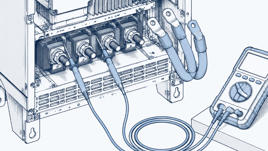
- Isolate, lock out and prove the bus is dead. Yaskawa's E7 warning is to remove all power, wait at least 5 minutes, check that the charge lamp is off, and then still measure the input, output and DC bus voltages before working inside (p. 6-21). The charge LED stays lit until the bus falls below 10 V DC. Measure across the bus on the meter's highest DC voltage range and carry on only below 10 V DC (p. 6-21). Other drives give other times. Check yours. Expect: bus voltage below your manual's safe level. If not: wait and measure again. Never test the output stage with the supply connected, as jraef put it on PLCtalk.
- Disconnect the motor leads, and the brake resistor if one is fitted. Danfoss says to disconnect all input, motor and brake resistor connections before the static tests (p. 88). For the inverter section it gives the reason: with the motor connected, a short in one phase reads in all three, so you can't tell which phase failed (p. 96). Expect: nothing connected to U, V, W except your meter.
- Find the DC+ and DC− test points. Names vary. On the E7 they're the ⊕1 and (−) terminals (p. 6-21). The Danfoss high-power units use a connector on the power card (p. 96). The PowerFlex 750 frames 5 and 6 use the DC+ and DC− bus bar terminals. Some smaller drives bring out no bus terminals at all; see the field notes below.
- Set the meter to diode test. Danfoss says an analog meter on the R×100 range also works (p. 88).
- Red lead on each output terminal in turn, black on DC+. This forward-biases the upper diode in each phase. Expect: a diode drop, the same on U, V and W. Yaskawa gives about 0.5 V (p. 6-23). Danfoss gives roughly 0.300 to 0.500 on a typical digital meter (p. 88). Rockwell's nominal for PowerFlex 750 frames 5 and 6 is 0.36. If not: near zero means a short on that phase. OL means that diode is open.
- Red on DC−, black on each output terminal in turn. This tests the lower diode in each phase. Expect: a diode drop again, matching across the three phases (Yaskawa p. 6-23; Danfoss p. 96).
- Reverse both: red on DC+, black on each output; then red on each output, black on DC−. These put both diodes in reverse. Expect: OL. The reading may start low and climb toward OL as the meter charges the bus capacitors (Danfoss p. 96). Rockwell says this climb can take several minutes. If not: a reading that stays low, especially near zero, means a shorted device.
- Compare the phases. Rockwell's service manual says readings vary with the meter. If yours aren't near the nominal values, check that each phase reads consistently. One phase that differs from the other two is the one to look at.
- Test the rectifier and brake IGBT too. On the E7 the same pattern applies to the input terminals R, S, T against the bus (p. 6-21). Not every drive's input reads like that: Rockwell's PowerFlex 750 table, for example, gives different readings on two of its input terminals, so use your own manual's values. Danfoss has a separate static test for the brake IGBT, between the brake resistor terminals and the negative bus (pp. 97–98).
| Red lead | Black lead | Healthy drive | Shorted device | Open device |
|---|---|---|---|---|
| U, V or W | DC+ | Diode drop, about 0.3–0.5 V, equal on all phases | Near 0 V | OL |
| DC− | U, V or W | Diode drop, equal on all phases | Near 0 V | OL |
| DC+ | U, V or W | OL, may climb slowly as the bus charges | Low and stays low | OL |
| U, V or W | DC− | OL, may climb slowly | Low and stays low | OL |
The table above is our summary of the Yaskawa, Danfoss and Rockwell procedures and the Semikron Danfoss note. The short/open columns come from the Semikron Danfoss note (p. 2). Your drive's manual may give different values or test points.
What if the diode test passes but you still suspect the IGBTs?
Keep going, because a pass isn't a clean bill of health. Danfoss says that, depending on how it failed, a defective IGBT can give good readings in the static tests (p. 97). There are three more checks, each a step closer to a powered test:
- Gate resistors and gate-emitter. Danfoss says that in nearly all cases a failed IGBT also takes out its gate resistors. Its manual gives a resistance check at test connectors on the gate drive card, with values per frame size (p. 97). With the module disconnected, Semikron Danfoss describes an ohmmeter check from gate to emitter. A healthy gate behaves like a capacitor: the reading rises quickly into the megohms and goes to OL. A damaged gate typically reads as a dead short to the emitter or collector. The gate is sensitive to static, so use ESD precautions (AN 20-003, p. 7).
- Output balance, powered. Danfoss's test measures phase-to-phase output voltage with an analog voltmeter, because digital meters can misread the switching waveform. All three readings should be within 8 V AC of each other. With a clamp meter, the currents should be within 2 to 3% of each other. If the voltage is unbalanced with the motor disconnected, test the gate drive signals (p. 111).
- Gate drive signals and switching. Danfoss's dynamic tests check the gate signals with the DC bus disabled. A single bad gate signal points to the power card, all six to the control card. A separate switching test checks that the IGBTs actually turn on (pp. 112–114). These tests need the maker's test cables and procedure; they're not something to improvise on a live drive.
What should you do once you've found a failed IGBT?
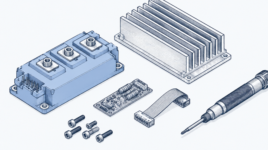
Replace the module, and find out why it failed before you power it up again.
- Replace by the manual. Danfoss says an incorrect reading in any inverter test means a failed IGBT module. On units with two modules it recommends replacing both, even if the second one tests good (p. 96).
- Don't just change the fuse. Yaskawa says never to replace the DC bus fuse without first checking all the output transistors (p. 6-22).
- Check the gate drive after the repair. Danfoss says that after an IGBT failure you should confirm the gate drive signals are present and have the correct waveform (p. 97).
- Look for the cause outside the drive. Danfoss lists repeated short circuits or earth faults, and running the drive outside its normal operating limits for long periods, as causes of IGBT failure (p. 97). A new module on the same faulty cable or motor may not last. Our suggestion, not a manual step: test the motor and cable with the drive disconnected, as in the overcurrent post, before you re-energise.
What does the manual say vs what has worked in the field?
| Manuals | Field reports | |
|---|---|---|
| Basic test | Static diode test of the inverter section, motor leads off (Danfoss p. 96; Yaskawa p. 6-23; Rockwell PowerFlex 750 frames 5–6) | PLCtalk, 2014: keithkyll: with the drive unpowered and the motor off, diode-test across the outputs; a shorted IGBT reads "close to zero Ohms". Practical Machinist, 2010: JC Chamberlin describes testing every input and output terminal against both bus terminals, calling .300 to .800 good and .000 to .100 a short. Both describe a method; neither reports a specific repair |
| Working live | Static tests are done without power, before power is applied to a suspect unit (Danfoss p. 85) | PLCtalk, 2014: asked how to check IGBTs with the input connected, jraef replied: "You do not. You can get killed." |
| No DC bus terminals | Not covered in the manuals read | PLCtalk, 2020: Jerry mahan, a motor-control instructor, couldn't find bus terminals on an Allen-Bradley PowerFlex 4. Lynx777 replied that without them you have to take the drive apart to reach the bus. alan_505 noted that many smaller drives combine the input diodes and output transistors in one block, so a diode failure means replacing the whole power module |
| Pass but still faulty | A defective IGBT can read good; check the gate resistors and gate drive (Danfoss p. 97) | No field reports found yet |
| Confidence | Official | Methods described by forum members. No confirmed repair outcomes in these threads |
Fault-code entry (summary)
| Field | Value |
|---|---|
| Topic | IGBT / output transistor failure in a VFD |
| Codes that can point to it | Siemens MM440 F0022 (DC link overcurrent = IGBT short, among other causes) · Yaskawa E7 PUF (DC bus fuse open), OC (includes shorted drive output) · Danfoss VLT Alarm 16 (short circuit), Alarm 13 (overcurrent, occasionally with IGBT misfiring) |
| Lookalikes | Failed current sensor (Danfoss p. 79) · MM440 I/O module not seated (p. 309) · motor or cable short (check with the drive disconnected) |
| Checks in order | 1. Isolate, prove bus discharged · 2. Motor and brake resistor off · 3. Find DC+/DC− · 4. Diode mode · 5–7. Each output to both bus terminals, both polarities · 8. Compare phases · 9. Rectifier and brake IGBT · then gate resistors, output balance, gate drive signals |
| Healthy reading | Diode drop one way (about 0.3–0.5 V on the manuals cited), OL the other, equal on all three phases |
| Failed reading | Near 0 V both ways = shorted; OL both ways = open |
| Never | Test the output stage with the supply connected · insulation-test the drive · replace a blown DC bus fuse without testing the output transistors |
| Manual reference | Yaskawa TM.E7.01 pp. 6-5, 6-7, 6-21 to 6-23; Danfoss MG.90.L1.02 pp. 60, 66, 78–79, 85, 88, 96–98, 111–114; Siemens MM440 Parameter List p. 309; Rockwell PowerFlex 750 TotalFORCE frames 5–6 service manual (online); Semikron Danfoss AN 20-003 pp. 2–7 |
| Last verified | 26 Oct 2026 |
Why write down the readings, not just "IGBT OK"?
Because "IGBT OK" can't be checked later, and a set of numbers can. If the job card records the meter used and every reading (each output to DC+, DC− to each output, and the reverse readings, with the motor off), the next engineer can repeat the test and compare. A phase that has drifted since last time stands out. If it just says "checked, OK", they're starting again. The same goes for why the module failed: write down the cable or motor fault that took it out, or the next module may go the same way. More on that in "it's running now" is not a fix.
How would you find this in your own archive?
If one of your drives has had an IGBT or power module replaced before, the readings and the cause are probably in a service report that says "F0022", "power module", "short circuit" or just "drive faulty". HangerSearch searches your own finalized service reports by fault code, machine or symptom. It shows the prior cases that match and why, and opens the cited page. Nothing is generated. See how that works for a repeat machine fault, and how we handle your reports.
Book a 20-minute demo: hangersearch.com
FAQ
What are the symptoms of a bad IGBT in a VFD?
The usual ones are a short-circuit, overcurrent or hardware fault that stays with the motor cable disconnected, a blown DC bus fuse, and rough running or stalling with unbalanced output voltage. Siemens lists an IGBT short under MM440 F0022. Yaskawa ties an open DC bus fuse to a failed output transistor. Danfoss links rough running to an IGBT misfiring. A failed current sensor can look similar.
How do you test an IGBT with a multimeter?
With the drive isolated, the bus proved discharged and the motor disconnected, set the meter to diode test. Measure each output terminal against DC+ and DC− in both polarities. One direction should show a diode drop (Yaskawa says about 0.5 V; Danfoss 0.3 to 0.5 V) and the other OL, the same on every phase. Near zero both ways means a short.
Can an IGBT pass the diode test and still be bad?
Yes. A multimeter can't switch an IGBT on, so the diode test mostly checks the freewheeling diodes. Danfoss says a defective IGBT can give good static readings, and that a failed IGBT nearly always damages its gate resistors too. Check the gate resistors, then output voltage balance and the gate drive signals.
Why must the motor be disconnected for the IGBT test?
Danfoss says that with the motor leads connected, a short in one phase reads in all three phases, so you can't tell which one failed. The motor windings connect the output terminals to each other.
Can I test the IGBTs if my drive has no DC bus terminals?
Not from the outside terminals alone. Forum members on PLCtalk say you have to open the drive to reach the bus, and that many smaller drives put the input diodes and output transistors in one module, replaced as a unit. Check the service manual for your model's test points.
Sources
- Yaskawa, E7 Drive User Manual, TM.E7.01. Read as a PDF from yaskawa.com on 26 Oct 2026. Supports: GF and OC causes and corrective actions, including running without the motor and checking for a phase-to-phase short at the drive output (pp. 6-4, 6-5); PUF, DC bus fuse open, caused by shorted output transistors or terminals (p. 6-7); the discharge warning, 5-minute wait, 10 V DC charge-LED threshold and bus measurement, plus the input diode test (p. 6-21); the DC bus fuse's role and "never replace the DC bus fuse without first checking all of the output transistors" (p. 6-22); the output transistor diode test, about 0.5 V and OL (p. 6-23). Paraphrased.
- Danfoss, High Power Service Manual for VLT FC Series, MG.90.L1.02. Read as a PDF from a distributor copy (automationplus.it) on 26 Oct 2026. Supports: rough running and IGBT misfiring, occasional Alarm 13 (p. 60); Alarms 13, 14 and 16 (pp. 65–66); unbalanced output with the motor disconnected pointing to the IGBTs or gate signal (p. 78); current sensor faults and the 1 A display check (p. 79); static tests without power, before powering a suspect unit (p. 85); meter type, disconnecting input, motor and brake connections, and the 0.300 to 0.500 diode drop (p. 88); the inverter section test, the reason to disconnect the motor, and replacing both modules (p. 96); causes of IGBT failure, gate drive checks after failure, good readings from a defective IGBT, and the gate resistor test (p. 97); the brake IGBT test (pp. 97–98); output imbalance test, 8 V AC and 2 to 3% (p. 111); gate drive signals and IGBT switching tests (pp. 112–114). Printed page numbers. Paraphrased.
- Siemens, MICROMASTER 440 Parameter List, 6SE6400-5BB00-0BP0, Issue 01/06. Read as a PDF. Supports: F0022 causes, including IGBT short-circuit, and the permanent-fault checks with the motor cable disconnected (p. 309). Paraphrased.
- Rockwell Automation, PowerFlex 750-Series Products with TotalFORCE Control Hardware Service Manual, Frames 5 and 6, "Perform Forward and Reverse Biased IGBT/Diode Tests for Frames 5 and 6": https://www.rockwellautomation.com/en-us/docs/technical/powerflex/_online/750-tg102/powerflex-750-series-products-with-totalforce-cont/component-inspection-and-tests/perform-forward-and-reverse-biased-igbt-diode-test.html. Read 26 Oct 2026. Supports: 0.36 nominal reading, readings varying with the meter and checking consistency between phases, OL readings that climb over several minutes as the bus charges, testing at the DC+ and DC− bus bar terminals. Paraphrased.
- Semikron Danfoss, Application Note AN 20-003, "Field Testing of Power Semiconductor Modules", Rev 01, 7 Oct 2024: https://assets.danfoss.com/documents/latest/444231/AB501643313479en-000201.pdf. Read 26 Oct 2026. Supports: the diode test as go/no-go, 0.2 to 0.5 V for power diodes, short reads near 0 V both ways and open reads OL both ways (p. 2); ohmmeter limitations and insulation testers damaging semiconductors (pp. 2–3); IGBTs can't be switched on by the meter, the freewheeling diode is what's checked (p. 5); IGBT forward/reverse check (p. 6); the gate-emitter check and ESD (p. 7). Paraphrased.
- PLCtalk, "How to check IGBT in siemens simovert vc drive", started by Amar88, 27 Sep 2014, replies from jraef and keithkyll the same day: https://www.plctalk.net/threads/how-to-check-igbt-in-siemens-simovert-vc-drive.90457/. Read 26 Oct 2026. Supports: the opening question and the quotes.
- PLCtalk, "Testing VFD diodes without DC bus terminals", started by Jerry mahan, 16 Feb 2020, replies from Lynx777 (17 Feb 2020) and alan_505 (21 Feb 2020): https://www.plctalk.net/forums/threads/testing-vfd-diodes-without-dc-bus-terminals.123795/. Read 26 Oct 2026. Supports: the no-bus-terminals field notes. Paraphrased.
- Practical Machinist, "A Good way to test an IGBT in an AC VFD", JC Chamberlin, 1 Apr 2010: https://www.practicalmachinist.com/forum/threads/a-good-way-to-test-an-igbt-in-an-ac-vfd.201624/. Read 26 Oct 2026. Supports: the field method and the .300–.800 / .000–.100 figures as he gave them.